Friday, 10 May 2019

Moving your server to the cloud - Google Compute Engine vs Amazon Lightsail

Ok, it's been so its been a while since I last blogged (really ?  four years? what have I been doing?!)
but I thought this was  good venue for making a few notes on the above.

WHY?

Use case;  I have a stocks database running on a hosted server that scrapes stock prices daily and adds them to a sql database for later analysis.

I used to just grab the website pages and decompose them in php, but more and more often data became unavailable because sites were rendered in javascript so that people like me couldn't use them (which to be thoroughly perverts the intent of the World Wid Web, but hey, capitalism and all that) .

Eventually I got around much of that by writing a python program that used the python webkit (and later webengine) to render the html so I could once again access the data. (BTW I believe Chrome can now run headless and achieve the same)

BUT my host didnt run a recent enough version of python. What to do? Well I looked at AWS (too expensive) and Google App Engine (too constrained) but Google's other product , Compute Engine, had a free demo, so here we went.

GOOGLE GCE


Although the networking and firewall config took quite a lot of sorting it was straightforward to load up an Ubuntu instance which could provide python webengine(I'm a Debian man, but their version was to old)  with a static ip so i could happily run a web service to do my page rendering.

However  it wasn't very fast, and fell over (as in no http or ssh response from the instance ) a couple of times for unresolved reasons.   The next level of performance was also getting costly, so time to try a new offering, Amazon's Lightsail.


AMAZON LIGHTSAIL

This was a doddle; no networking issues, just load up my Ubuntu 18 instance ,  complete with LAMP (via apt-get, they have a LAMP add-on but it is too old) and bingo!

36 hours later, no response from server ! crap - is this an Ubuntu thing?  When it happened again,  I deleted the instance and loaded a Debian 9.5 instance instead.  Just as quick to set up, and noticeably quicker than the Ubuntu under my meagre (but free) 600mb memory limit

Friday, 3 April 2015

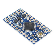
Arduino Pro Mini 3.3v + TFT 2.2" colour scrren


Want to have a fully functioning colour display microcomputer for a few bucks, and running off solar cells or three aa batteries?

Easy - enter the 3.3v version of the Arduino Pro mini. It can drive a cheap 3.3v colour 2.2" TFT screen via SPI

theres a very good howto HERE (yeah, a proper howto, not some fucking Youtube mess) - only thing you have to note is that the Adafruit-GFX-Library has to be renamed Adafruit_GFX  (yes thats underscore) for the sketch to work (so why didn't they call it that in the first place?)

Google is your friend for the Pro Mini details - the 3.3v version is a bit tricky to program the way i did it (from a 5v Uno, which has a 3.3v pin) but THIS howto got me sorted, programming it via the SPI/ICSP route with resistors in the SPI lines.

Yeah, its not as simple as the Picaxe, but fucking amazing really for a few dollars and bugger-all components.

Sunday, 28 September 2014

Recycling HDPE and PP Plastic

I've been playing around with my old lathe a lot lately (its a pre-WW2 Myford ML1 museum piece, slop everywhere, but its surprisingly useful for working in soft metals and plastic), and browsing Youtube to that end.

But an article about recycling HDPE (high density polythene) into blocks for machining purposes really piqued my interest, as I am always on the lookout for plastic scraps to use for machining stuff.

The great thing about HPDE and PP (Polypropylene) is that they are both quite durable plastics; not too brittle like melamine and perspex (acrylic) can be . They both also melt at low temperatures and don't give off any toxic fumes while doing so.

A bit of experimentation in the oven found that HDPE melts at round 180 C, PP at 200; though these can vary a bit according to the exact sample. The HDPE (recycle code 2) comes from plastic milk bottles and the PP (code 5) from ice-cream containers! When I say melt, it is doughy rather than fluid, but quite workable.


Once out of the oven, it hardens quickly so you have to work fast. I made up some 5mm spacers out of ally tube so I could squish the blob between two boards, and the spacers would maintain the resulting sheet at a consistent thickness.


 As you can see due to insufficient care I ended up with a crease or two where the material was under that thickness, but apart from that it was bang on, so I decided to press (!) on; It was for a boomerang, so I could carve the thickness down a little to remove the variations. Incidentally PP remelts fine, so if you stuff-up, just re-do the process. HDPE seems a little more difficult to re-melt; I haven't yet established how much higher in temperature I need to go for success.

I had laid out the material to be melted on the oven tray in the rough shape I needed, to avoid waste, and it was easily cut out from that.


I'm really excited about all this; at last I don't have to make do with materials and thicknesses that aren't suitable, as I can control that; and all I have to do to get them is eat a lot of ice-cream!  win-win, as they say.


Monday, 16 December 2013

Low Budget Remote Solar Powered Computer Controlled Sensor

I got interested in having a sensor at the bottom of my garden, sending things like wind speed, temp, etc. wirelessly to a logger.

Yes I know that if I spent a few hundred bucks I could have a weather station that does that and more , but where's the challenge in that?

Particularly when I found without too much googling that a fellow kiwi, Stan Swan, had sussed it all out quite a while ago, using a picaxe single chip computer and cheap chinese parts .

I soon realised that this clever little chip would lend itself to solar power rather well, and that those cheap-as-chips chinese solar-powered garden lights would be just the ticket.

Mods to the garden lights were simple; The lights were in the form of a twist-off self-contained solar unit above the redundant lens / garden stake. Snip off the (unnecessary but potentially handy ) bright LEDs, slide two wires for external connection thru the vacant hole and solder to the terminals of the 1.2v nicad that powers the unit. wire in series, and bingo - 3.8v of self-contained power.

In my next post I'll detail the Picaxe / ASK wireless work , with as-built code and diagrams; but if I am delayed, be assured that Stan's docs have it all in there, and it works.

Sunday, 24 November 2013

Presenting - the Variorang!

Variorang - config 1


Variorang - config 2

The photos explain it all, really - a boomerang made out of strips of material (in this case polypropylene, a really good material for boomerangs)
joined with screws and pins.

I'd wondered when making my first booms the traditional way (cutting a flat shape from sheet ) whether joining strips with a simple overlap joint would be feasible, since it creates a boom with a layered 3D shape; would it fly?

Then i saw a number of "pocket knife" type booms on Pierre Boillon's site, and that answered my question.


It was obvious once I considered this method of construction that it lent itself to the creation of a design of boomerang the geometry of which is very easily modified;  a central screw allows elements to rotate to any desired angle, and pins pressed thru the elements lock them in position; to change the shape again, just re-pin.

I added the "winglets" not just for more variability,  but also because I needed something for balance at the end of the main arms to compensate for the weight of the added screw joining the two arms.

Tuesday, 1 October 2013

Boomerang making part 2; a few mis-steps.

As mentioned in my previous post, difficulties in finding suitable materials has played a large part of my self-education in the practice of making boomerangs.  A secondary aspect has been the fabrication side.

My first foray into the sphere of lap-jointed boomerangs, for example. Wood would (!) seem an ideal material, light but rigid.  Since NZ is home to some of the world's largest Pinus radiata plantations I rather unsurprisingly chose to make mine out of that (radiata pine).

The lap-jointing, courtesy of some careful sawing,  went surprisingly well, and i ended up with quite a nice looking, relatively light boomerang. However in the process of planing what was a 10mm thickness down to 5-7mm (= a lot of shavings!) and subsequent shaping exposed a difficulty in maintaining a sufficient joint strength. On an early test flight, a mild crash broke the rang on a part of the joint. dang!   I'll try that again some time.

Meanwhile, the idea of moulding my own cloth-reinforced resin rang had taken hold.

I had some polyester potting resin on the shelf;  add some strips of polyester/cotton tee-shirt, a plasticine mould built on a foil-covered board in the outline of my selected plan, and presto!  ...oops, whats this?  my composite rang is a rubbery flop! not enough hardener?

Monday, 16 September 2013

More on boomerangs - the making of them.

Once I got into the subject of boomerangs I was soon fascinated by the scope of the topic. Combining the skills of technology, craftsmanship and creativity,  the making of boomerangs is more art than science, but no less alluring for that.

The first art to boomerangs is that of actually throwing them, and in the absence of any expertise in my neighbourhood I had to resort to the internet for some help.

Of course the easy path is to go buy one; even boomerangs have their mass-produced commercially available models.
The Aussie Magic, a typical A-pattern sport 2-blade boomerang


But since when did I choose the easy way? Attempting to achieve a good returning boomerang by building them at the same time as I learn to throw them has definitely complicated the whole exercise, but hey, I have the time, so why not.

MATERIALS

One issue I have struck early on is that of the suitability of materials. Ideally the material should be light enough to fly well (weight can always be strategically added), durable, adequately rigid in narrow thicknesses, and easily worked.

Another self-imposed criterion is that the material should be readily available and easily affordable, to avoid my research becoming too expensive.

Plastics of various sorts are an obvious option. My first problem is understanding what material I am using; for example one of my first boomerangs was made from a 4mm kitchen chopping board. It is a waxy translucent material, fairly dense and therefore a little heavy, but easily worked; I think it is polypropylene. PVC (polyvinyl chloride) is another possibility. I have also used ABS (acrylonitrile butadiene Styrene). Polystyrene is a little brittle, melamine even more so.

I also intend to experiment with creating my own reinforced resin laminates, so I can achieve the required attributes.

I also intend to explore the use of aluminium extrusion, as aerofoil-shaped sections are available quite cheaply. I believe that metal boomerangs are not used for safety reasons in competitive boomerang events, but that is not an issue for me at the moment.

DESIGN

There are a myriad of designs to draw inspiration from. the early design decision is the number of effective blades the boomerang should have; four and three-bladers are general suitable for short fast accurate flights; I personally find the two-bladers,  traditional or otherwise,  for long range slower flights, more intriguing.

FIRST ATTEMPTS

The first design I attempted to build was an A-shaped 2-blader similar to those pictured above, called Aussie_Round, as the plan showed appropriate airfoil cross-sections.

I built two, one in 3mm pvc, the other in 4mm pp; The latter I got flying fairly well, until a recent careless throw landed it firmly in a treetop, where it hooked over a branch and will need a decent storm to dislodge.

CONSTRUCTION

I found construction to be a quite straightforward:
  • download pattern and scale to required size
  •  print on A4  paper (make sure print size is a full 100% ),  and cut out paper pattern  (paste together several sections if larger than A4)
  • tack pattern to material and transfer outline
  • cut out outline with jigsaw
  • carve aero profile with surform file, and scrape smooth with craft knife

The scraping is used because trying to smooth these plastics by sanding produces a furry mess, whereas scraping works well.


THE LEARNING PROCESS


Insolite - 3mm abs version
  Insolite (a small weighted 2-bladed design by P Boillot - see my index of his plans) in 3mm abs - this version of abs was a bit brittle, and the rang broke on a crack introduced while fabricating.
Insolite mkII - 1.5mm polypropylene


A version in 1.5mm polypropylene proved too flexible, and unstable.

Saturday, 24 August 2013

It's a bird, it's a plane, no , it's a ....boomerang?

Trigger boomerang
George Dimantiev's "Trigger" mta boomerang.

Yup, it's nothing like the Australian aboriginals bent sticks we all know as boomerangs, but that's what it is.
Did you know that experiments have proved that boomerangs still work in outer space? i.e. the basic mechanics are more to do with physics than aerodynamics, although here on earth the latter does come into play.
 
My interest in boomerangs started a few weeks ago as a lightbulb moment during thoughts about how to keep Pukekos out of our vegetable patch; Pukekos are a sort of avian combine harvester, and our plastic bb gun wasn't fierce enough to deter them, on the rare occasions of a direct hit.

Actually it started long before that. When I was a kid, at one stage a cereal manufacturer actually gave away small plastic boomerangs in their cereal boxes, and I recall hours of fun flying my Weetbix Boomerang.

I haven't got anywhere near accurate enough with them, but is been fascinating research.  like almost anything, boomerangs have evolved a competitive sports element, where distance , accuracy, and mta (maximum time aloft) are competed for.

Interest in boomerangs seems to have waned in recent years, which is a pity, for their creation combines elements of art, science, and craft.

A guy called Pierre Kutek has kindly created a big collection of plans, and another Pierre, Mr  Boillon, has an even larger gallery of thousands of different designs - he's even reviewed their performance. I've take the liberty of loading his index into a database and created a report so I can sort by name or his boomerang performance score.

Tuesday, 12 February 2013

Computer Case Mod as a straight six engine!

computer engine - rhs view
Computer Engine, rhs view
computer engine - lhs view
Computer engine, lhs view showing leds firing.


This is my customised computer case, made to look like a straight six engine :-) here's a short video of it.

I'd seen a superb V-8 case, but since my car background covers Triumph TR6, GT6, and then a series of 240Z's, I knew I had to do a straight six version! 

I built a sequential flasher unit to fire the led 'spark plugs' - yes I know, real sixes fire 153624 not 123456, but this looks neater LOL

and yes, I have to admit, one old vacuum cleaner was slightly hurt in order to supply the polished stainless steel intake manifold tubes, and exhaust pipes.

I wasted countless hours cutting down and painting a tower case to a lower profile before deciding that I'd screwed up the cooling by putting the power supply over the heatsink.  Eventually I gave up and swiched the bits over to a std desktop case.  I could have kept all the manifolding on one side so I could park the case against a wall or something, but the "crossflow" version looked better.

I am going to add leds to the 'pulley' fan, and who knows maybe a servo-driven throttle flap to that manifold!

Feel free to suggest improvements, as long as they don't have the words "trash compactor" in them.

Friday, 19 October 2012

PC Hall effect sensor parallel port interface

This is a circuit I built as a rev counter for my wind turbine experiments. I  started using a LED and MEL12 phototransistor, but sunlight played havoc with that, so I went to a Honeywell SS443R hall effect sensor plus a small magnet.

The circuit I used only required a few mods to work with the 443, and here it is (click on it to download a larger view):
I powered the circuit from a USB port,since it was easy to get to, but a takeoff from the pc power supply would work too (Black and Yellow wires from pc disk drive plug)

It might be possible to use the 443 without the LM339, but since I was already using it I kept it. You can add a second interface via pins 5&6 of the 339 outputting to pin 1, which connects in the same way as pin 2, only to pin13 of the parallel port instead of 12. This is how I compared versions of my wind turbines.

Be aware that the parallel port status byte address varies between pcs, normally using either x378 or x3bc, so you will need to test which you have.

I have included the c code for my parallel port monitor program below: it outputs lines to a file that look like this:
2011-07-25;16:44:57;Port1:;8rpm;Port2:;31rpm

Theres a part in the middle that you can ignore that also does a "wget" to send to a web server
//==================================================
// monitor parallel port  input pins (11,12,13,15) and count time between pulses
// must run with root privileges or will segfault
// parallel port addr +1 = input status byte
// bits 4567 = pins 13,12,10,11 respectively
#include <stdio.h>
#include <sys/io.h>
#include <time.h>
#include <sys/types.h>
#include <string.h>
#include <math.h>
#include "../c_headers/myutils.h"
#define IOPORT 0x0378
// #define IOPORT 0x03bc
#define COMMAND  "wget -q -O /tmp/wget.txt "
#define CMDTAIL  "'  >> /tmp/data.txt "
#define WEBADDR  "http://192.168.0.1/cgi-bin/ppmon.sh?data="
#define LIMIT 50 // sense test -variance allowed between readings limited to 50%
FILE *fp;
struct timeval  IntervalStartTime,  *pst;
struct timespan {
struct timeval StartTime;
struct timeval EndTime;
double TimeElapsed;
int avgrpm;
int lastreading;};
struct timespan Port1,Port2,period, *ts; double Tested,Interval=10.0; // display interval is 10 secs
// function prototypes here
void CalcElapsed(struct timespan *); void PeriodCalc(struct timespan *); // time for period
void WriteLog(char *);
main() {
unsigned char c,p,port;
char dbuff[20], * dbuffp; // date/time array & pointer
char data[64],* datap; // data line buffer & pointer
char cmd[128],* cmdp; // cmd buffer & pointer
char  *argv[64];       // command line argument array (for runcmd func) int result,samplecount=0;
double duration;
int iobase=IOPORT; Port1.avgrpm=Port2.avgrpm=0;
/* Get access to the ports */
if (ioperm(iobase, 3, 1)) {perror("ioperm");}
gettimeofday(&period.StartTime, NULL); // get start time
Port2.StartTime=Port1.StartTime=period.StartTime;      // init timers
int last_status=0;
int p1avg[10],p1index,p2avg[10],p2index;
while (1) // must ctl-c to exit
     { //     c=inb(0x0379);
     c=inb(iobase+1);
     if( !last_status ) {last_status=c;} // init last_status if first time thru
     if( c != last_status ) // keep reading port until change
 {
  last_status=c; // save latest status as last
  if ( p = c & 0x30 ) // pin 12 or 13 set active? (low)
    {
     if ( !(port = (p ^ 0x20))) // if its pin 12
 { // work out when this pin last set active (=pulse time)
// tscalc.StartTime=Port1StartTime;
ts=&Port1;
PeriodCalc(ts);
printf("Port 1: %5.6f : %d rpm %d avg\n",ts->TimeElapsed,ts->lastreading,ts->avgrpm);
 }
     else
 {
  if ( !(port = (p ^ 0x10))) // if its pin 13   {
ts=&Port2; PeriodCalc(ts);
printf("Port 2: %5.6f : %d rpm %d avg\n",ts->TimeElapsed,ts->lastreading,ts->avgrpm);
}
 }
} // exit pin-active section
 } // exit port-changed section
// tscalc.StartTime=IntervalStartTime;
ts=&period;
CalcElapsed(ts);
if (ts->TimeElapsed> Interval) // has interval elapsed? if so, ...
{
// if both ports non-zero, (ie have had readings sent) do output if  (Port1.avgrpm>0&&Port2.avgrpm>0)
 {
   printf("Status: Port1: %d rpm; Port2: %d rpm\n", Port1.avgrpm, Port2.avgrpm);

dbuffp=&dbuff[0]; //store date,time
GetTime(dbuffp); strcpy(data,dbuff); // copy date,time into data line
sprintf(data+strlen(data),";Port1:;%drpm;Port2:;%drpm", Port1.avgrpm, Port2.avgrpm);
puts(data);
strcpy(cmd,COMMAND); // copy command prefix to buffer
strcpy(cmd+strlen(cmd),WEBADDR); // copy url into cmd line
strcpy(cmd+strlen(cmd),data); // copy data into cmd line
// DEBUG puts(cmd);
parsecmd(cmd,argv); // set up argv array for runcmd
runcmd(argv); // run external command and return
strcpy(data+strlen(data),"\n"); // append cr
WriteLog(data);  } ts->StartTime=ts->EndTime; // reset interval starting time } // end interval-elapsed processing
    } // ctl-c exit
}
void CalcElapsed(struct timespan *ts) // elapsed time to millisec accuracy
{
long seconds, nseconds;
gettimeofday(&ts->EndTime, NULL);
seconds  = ts->EndTime.tv_sec  - ts->StartTime.tv_sec;
nseconds = ts->EndTime.tv_usec - ts->StartTime.tv_usec;
ts->TimeElapsed = seconds + nseconds/1000000.0;
}
void PeriodCalc(struct timespan *ts) // time for period
{
CalcElapsed(ts);
int result = ceil(60 / ts->TimeElapsed);
// only record sensible time, else just replace prev reading
if(ts->lastreading>0)
 {
  int pctvar = 100*abs(result - ts->lastreading) / result; // test within variance tolerance
  if(pctvar < LIMIT)
     { // if avgrpm not 0, update average rpm, else just insert
     if(ts->avgrpm > 0)
        {
 ts->avgrpm=ceil((ts->avgrpm+result)/2);
 ts->lastreading=result; // save this reading
}
     else {ts->avgrpm=result;}      }
  else
{printf("variation error: last: %d rpm; this: %d rpm\n", ts->lastreading, result);
 ts->avgrpm = 0;
 ts->lastreading=0; // save this reading
}
  }
else { ts->lastreading=result; } ts->StartTime=ts->EndTime; // save end time as new start
} void WriteLog(  char *line)
{
fp = fopen("/tmp/data.txt","a");
if (!fp) { perror("error creating file"); }
fprintf(fp,line,"\n");
fclose(fp);
}

//=================================================

Tuesday, 15 November 2011

Comparison of Savonius variations

Having built models of the designs i wanted to test,I then monitored their performance over  a few hours.

Base for the comparison was a cup-type anemometer


the first model was a std Savonius design


next came a split 4-bladed version


lastly a revised version of the last design, only with zero overlap
(as suggested in my previosu postings, I was curious about whether any more lift effect might be gained)


 Here are the results

Summary / interpretation of results

Well it seems my alternative designs  werent a radical improvement on the original!

I'm a bit mystified by the ripple in all plots around the 17rpm (of the base anemometer, which I must get around to calibrating in mph!) mark;


Wednesday, 9 November 2011

Computerised Monitoring of Wind Turbines

I had assembled all these interesting VAWT designs - but which was best for my purposes?

If I had sufficient resources,  just hooking prototypes of each design up to some sort of electrical generator and measuring output power at various wind speeds would give me the answers I sought.

I settled for the cheap alternative:  build small scale models and measure the rpm of each for those various wind speeds.

I said "cheap" but I didnt say "quick" - in fact this lead me off into a LOT of sub-projects, all measured in weeks rather than minutes: build a basic cup-type anemometer wind vane; work out how to measure and record its rpm (and that of the candidate wind turbine model under test) via an electronic circuit coupled to my computer's parallel port; Write software to monitor the parallel port for those signals and record them at regular intervals.

caveat; my electronics knowledge is sketchy at best, and any prototyping of circuits is always accompanied by puffs of smoke at regular intervals marking the demise of yet another semiconductor.

At first I tried to use a combination of leds and  opto transistors, with a light-beam chopper to detect rpm, but I had so much trouble with extraneous light affecting the sensor that i gave it away in favour of magnets and hall effect sensors.

I used the Honeywell SS443R sensor because - well they were the only ones I could find , and a guy called Hadley Rich, who runs a small company called Nicegear that deals in stuff that crazed inventors like me like to tinker with, got them to me without hassle.

I had already got the opto sensor hooked into the parallel port (pins 12&13 for the 2 separate sensors, from memory, + pin 25=common GND ) via a LM339 comparator so left that in place and just swapped the hall effect sensor in place of the opto sensor on the input side of the LM339. It may be possible just to hook the sensor output (active low) straight into the par.port input pins. I'll put up a drawing of the circuit real soon. (postscript: done this , see later blog)

Then it was a case of a bit of C code to interrogate the parallel port and detect any change of either input pin (remembering that there are a couple of standard addresses for parallel  ports, ox378 and 0x3bc, both commonly used)

I even sent the data to the web server of my router, where another program (php this time, arent I versatile!  ;-)  ) recorded and graphed it for me.

For a more useful analysis I sorted a coupla hours worth of readings by base (my cup anemometer) wind speed and plotted the average speed for each test model against that anemometer.

Next post: the results!  exciting stuff, eh???


Some Variations on the Savonius VAWT

MY DESIGN

Looking at the benesh rotor, it occurred to me that if I removed the flat parts, I could insert another rotor at right angles. This would look very much like that furling rotor design that I linked to in my first post, with the added advantage of the thrust from the exiting airstream that is a feature of the standard Savonius.

So the rotor would look like this (left)


and the airflow would  look like this (below; green arrows show rotational direction)


I set the blade offset as for the optimum offset for the Savonius, which has been shown to be between .15d and .2d, where d is the DIAMETER ie twice the radius, of the blade arc. The blades are 1/4 of a cylinder, so arcs are 90 degrees.

But wait, theres more! I further wondered what would happen if I removed the offset - see diagrams below


The orange arrows are my prediction of wind flow, with much less thrust on the far side of the flow, but that blue arrow shows the lift that I hypothesise would be generated.

SO I would expect pattern 2 to be inferior at low speeds but could it catch up and even surpass pattern 1 at higher speeds?  Only one way to find out - build 'em and measure!

Doing this lead me into new fields of measuring turbine rpm at various wind speeds.
Doesnt look like the wind powered pump will be going this summer  -apparently Lao Tzu said that a good traveller has no fixed plans and is not intent on arriving - I suspect that he would be more impressed by my journey than the missus.

Tuesday, 8 November 2011

VAWT options

well lets start with the Savonius and its variants

now when I refer to the Savonius I am talking about those vawts with bucket-shaped vanes (essentially drag turbines, although there are certainly some lift characteristics in more advanced versions) that specifically direct the outgoing airflow onto the opposite vane, forcing it INTO the oncoming wind, as shown on the left,

as opposed to that on the right, which strangely enough seems to appear mainly in HAWT articles in a dismissal of VAWTs - shows how much they have thought about things - note the lack of the reverse-thrust effect.

A cut-down version as shown below left may be even more efficient , with perhaps the ultimate version being this Benesh profile , ( below right)
Benesh rotor


Optimised Benesh rotor


 I havent found comparative data, although somewhere i have seen research that shows that a three-blade savonius is actually LESS efficient, contrary perhaps to expectations.

but before I go further, i thought that this furling savonius idea ingenious.


The Savonius type VAWT seems suitable for my planned application (mechanical pond pump) because of its low-speed, high-torque nature.

But electricity generation requirements move in the other direction, to high-rpm relatively low-torque designs, using lift-based aerofoil-blade designs (Darrieus type).

Quiet Revolution helical turbine.
One of the most elegant is surely the Quiet Revolution product .

Most of the latest machines, more than a few coming from China which seems to be where all commercial offerings are originating, use the same blade type in a simpler vertical arrangement of 3 and more blades, also known as a giromill.

I plan to investigate the giromill type further, if I get as far as an electrical pump, but  for the moment I'll go with the Savonius types - more in the next post.


Lets start here

not that you would get anywhere if you did start from here, mind you.
My ancestor, homo meandertalensis!


THE PROJECT

I have a goldfish pond. Its continued health requires water circulation via a pump. Currently this is via a 12v dc electric pump consuming approx 40w of juice.

Its actually a bilge pump, as I didnt want to pay the ridiculous amounts being asked for purpose-designed jobbies that would deliver the required 1m head (to a waterfall)

Now 'er-indoors resents any power at all being wasted on such frivolous pursuits when it could be powering endless reruns of  game shows. Solar power is an obvious answer, but those panels arent cheap and home construction a bit beyond me. Wind power? well thats another matter!

CHOOSE YOUR WEAPON

The expert opinion is unanimous - stick a HAWT 100 feet or so in the air, and I'd have enough juice left over to power my computers (given the reliability of the local power, this is tempting)

HOWEVER the cost of safely mounting anything that high, and attendant visual pollution, rule that out.

I did consider a lower level HAWT, driving a purely mechanical pump in the same way the old american windmills used to - even got the thing half built. more on that another time, perhaps.

But theres something about the simplicity of VAWTs that appeals to me, especially considering we're on the side of a hill and the wind currents are all over the place. That sounds like VAWT country to me.

The SAVONIUS is an obvious choice, particularly if I stick with a mechanically driven pump (an alternator driving the existing electric pump would be a more flexible option - again, maybe later down the track)

but its a bit basic looking - the idea of the turbine having a a decorative sculptural aspect appeals, and there are plenty of elegant VAWT designs - such as the Ropatec, ....

And then theres the Savonius derivatives, Sandia, Benesh, etc

which to choose??!!   more on that soon.